|
I Interned at the exploration division of Honeybee Robotics in Pasadena, California during the summer and fall of 2012. The exploration division of Honeybee Robotics specializes in the development of drilling and sampling systems to be used on the Moon, Mars, or asteroids. The highly experienced team at Honeybee has had three dust removal or sampling tools sent to the surface of Mars and one sample processing system. It was a distinctly different experience from my NASA internships beginning on day one. There was no lengthy IT or safety training I was shown my computer, given a list of requirements for my first drill, and got to work. It was a refreshing change from my previous experiences. Requirements: The goal was to develop a drill which could be deployed from one of the small payload containers embedded in the wheels of the Jet Propulsion Laboratory (NASA/JPL) Axel prototype Mars rover and drill into the side of a cliff. These are the basic requirements given when I began my internship:
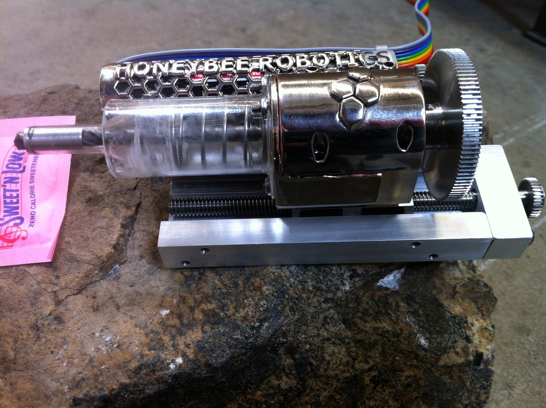
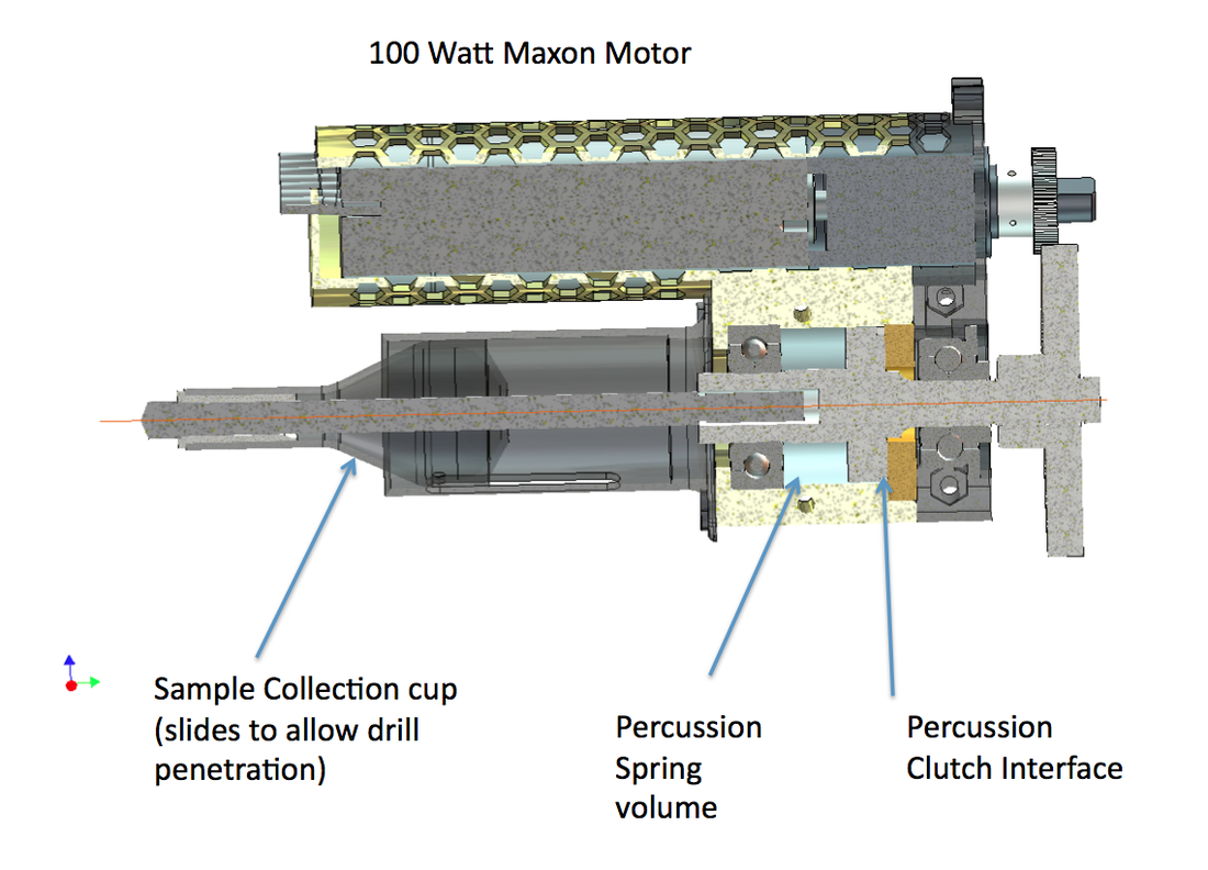
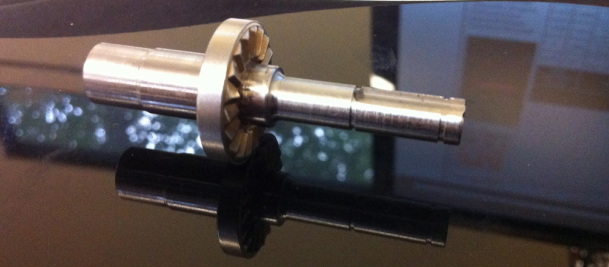
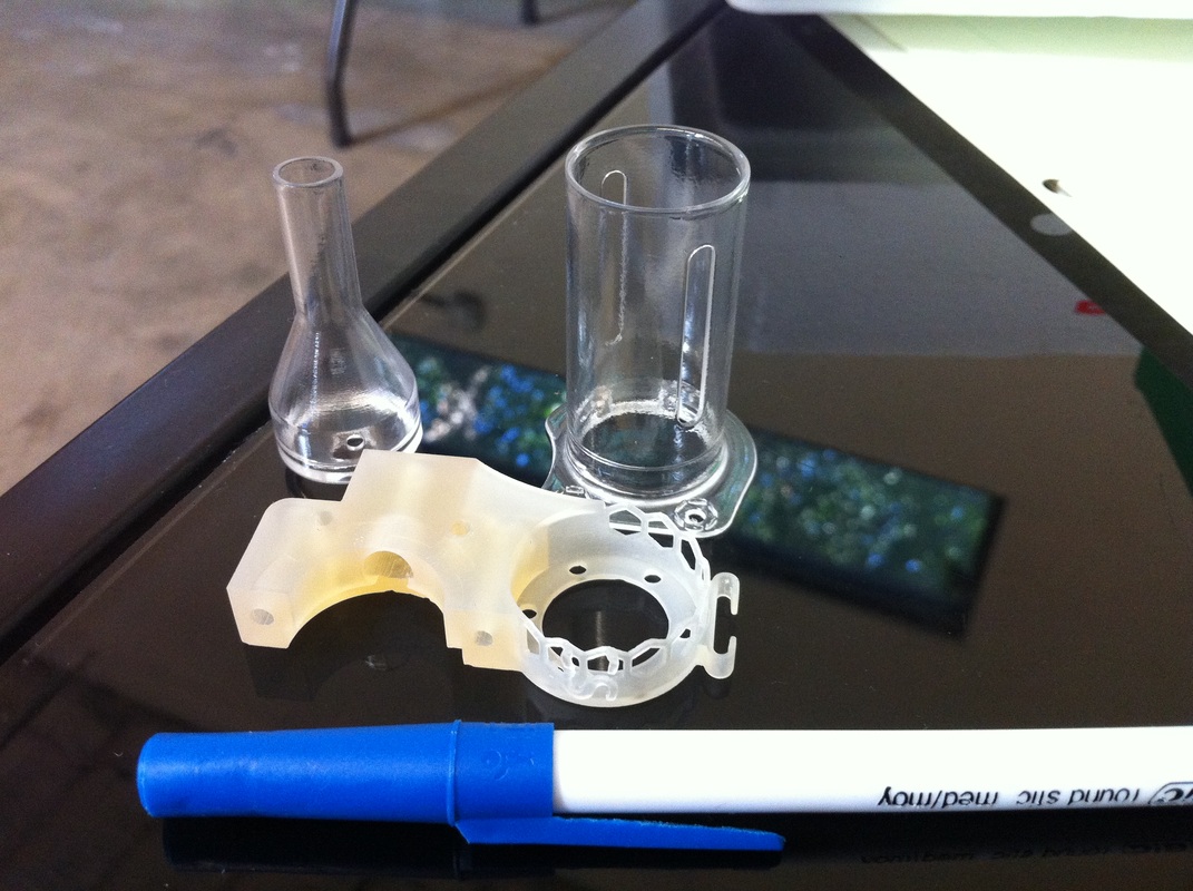
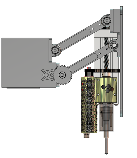
Design: The drill bit I needed to use had already been selected, a Relton Groo-V 1/8 in bit, which is very effective drilling into hard rocks, especially when combined with percussion. Most of us are familiar with rotary drilling, it is what is commonly used for drilling wood, metal, and other materials. Rocks are extremely hard and brittle. Hammering the drill bit into the hole introduces cracks in the rock, making the material much easier to cut. This results in significantly faster penetration rates, lower energy consumption, and a reduction in bit wear. The drill bit is much tougher than the rock, even though it may not be much harder. This is important because some rocks (such as saddleback basalt) have a compressive strength of 280 MPa, significantly stronger than even the best concrete. Percussion is even more important for drills going to other planets, because water cooling isn't an option. In the design of the drill, it was decided to use off the shelf parts wherever we could, so a much larger Hilti hand-held rock drill was disassembled to see what parts might be useful. We chose to reuse the percussion clutch components because of the difficulty that it would take to manufacture new ones. The percussion clutch components in the Hilti drill were made out of hardened steel and also had a coating on them, making them very strong and abrasion resistant so the pieces could be slammed against each other many times. Recycling these components saved money and time. Integrating these COTS components added some difficulty to the drill structure. The stationary part of the percussion mechanism (not shown) has a lot of sharp edges where it was fixed into the drill. The Hilti drill used an injection molded plastic piece to retain that part. Modifications to the percussion clutch would have been very difficult due to the small size and hardness, and it also be difficult to make a negative of that shape in aluminum to secure the part. This led me to 3D print the clutch fixture out of plastic on an SLA machine. While in the process of designing the drill components I concluded that since I needed one small part of small drill 3-D printed, I may as well print the whole thing. For the drill rotation and percussion I chose a 100 Watt Maxon motor with a diameter of 22 mm, and a 10 mm Maxon motor for advancing the stroke. The drill motor was integrated to the 3D printed chassis and the stroke motor (Z-axis) was mounted to the back of the linear slide. The drill motor had an integrated 2 stage gearbox but still needed an additional reduction of 3:1 for the output. It was a packaging challenge to fit the gears in such a small space but I was able to make it fit, and the flexibility of 3D printing to fabricate any geometry helped. The sample was collected inside another plastic container, shown above, and was extracted from the drill by rotating in the other direction to deposit it. The percussion worked in both directions and was also a great help in removing the sample.
Results The final product was delivered to the Jet Propulsion Laboratory in 3 months. During field trials, it was proven capable of drilling through multiple rock types and collecting samples from horizontal and vertical surfaces. Honeybee Robotics had never made a smaller drill, nor one that was as inexpensive as this one, the project was far under budget. Lessons Learned While the project was a success, it did not come without some lessons that were learned the hard way. Recycling components from other products can be great, but you don't always know what you are getting. Our machinist found that the rotary percussive mechanism was hardened not just on the percussive surface, but almost everywhere. As a result one of the tapped holes had to be made with an EDM. Luckily, this operation was only $75. In the first picture you can see a bright nickel coating on the housing of the drill. Although this certainly added some style, I regret doing it and wish I had skipped it. The plating mask was complicated and the vendor was not able to do it. The vendor should have refused, but attempted anyway and added a month long delay to getting my parts. The plating build-up was much thicker than it should have been and the part required light machining so the motor could fit. As a result the vendor learned a lesson as and stopped offering that service with masks. I learned not to make intricate masks and get a sanity check before trusting if a vendor can perform as advertised, especially when it is through a subcontract. Finally, I learned to do more planning when taking on a project, and resist the urge to begin modeling and engineering right away.
0 Comments
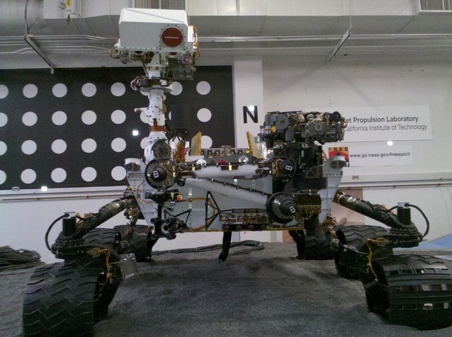
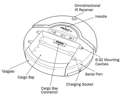
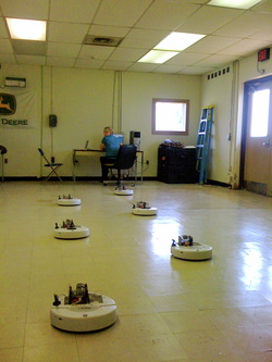
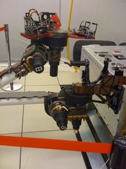 I actually took this photo myself. I actually took this photo myself. In the summer of 2009 I got the amazing opportunity to be an intern at the Jet Propulsion Lab as a rising junior. To make it even better, I was lucky enough to be part of the most exciting, scientifically promising, and coolest space project that was happening anywhere in the world - The Mars Science Laboratory. I was assigned as an Intern to the Surface Sampling Subsystem (SSS) and was Mentored by Daniel Limonadi and Jason Feldman. Daniel was the Validation and Verification Phase Lead for SSS, and Jason Feldman was the JPL project manager for the Sample Analysis at Mars (SAM) instrument. The SSS system includes the rovers arm, all of the attachments and appendages on the arm (including everything on the turret), the spare drill bits on the front over the rover, and the analytical instruments inside the rover which will process the regolith (soil) samples. The purpose of my project at JPL was to perform software testing for the two analytical instruments which were onboard the Mars Science Laboratory. These two instruments are called SAM and CheMin. 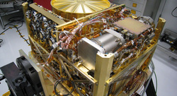 SAM. In all her glory. SAM. In all her glory. SAM is the largest, heaviest, and most expensive instrument on-board the rover, and will also be the most capable scientific instrument ever sent to the surface of another planet. It contains a quadrapole mass spectrometer, a tunable laser spectrometer, and a six-column gas chromatograph. It really is a very impressive chemistry laboratory in a box. A box which is now inside the rover Curiosity, and will soon be on Mars. The other analytical instrument on MSL is called the Chemistry and Minerology instrument, or better known as CheMin. I did functional level testing of the software in two different ways. I did most of my work on a software simulation of the hardware and operating system. This system was called WSTS (Work Station Test Setup), and allows developers to quickly test software right from their desks. This is a huge benefit to expedite development. I also tested software on hardware simulations, which were kept in the test-bed and were ESD sensetive. This allowed me to compare my results, and I could not only test to make sure that the current software release for the two instruments was functional, but also evaluate the fidelity of WSTS by comparing the results. I didn't always have an easy time with this project, I had a lot of learning to do about software testing and testing in general as I designed and developed the tests. I also needed to learn how to use a lot of tools in order to actually perform the tests. I was able to use scripts to turn command lists into batches that could run so I did not have to enter each one individually. This last summer (2010) I was lucky enough to be part of the 2010 NASA Robotics Academy at Marshall Space Flight Center in Huntsville, Alabama. There I was partnered with other college students from around the nation who also had a passion for robotics. Some of them were already experts in their field, and had extensive robotics experience. I was placed on a team with three other students, and was assigned to work on a distributed swarming robotic system under Dr. Robert Ray. Our goals were to develop a swarming system based on the iRobot Create platform, and have the robots autonomously interact and cooperate with each other. The iRobot Create is made for robotic research and experimentation, and is simply the Roomba without the vacuum cleaner, but with a cargo bay to add your own stuff and a 21 pin connector to interface with the Create. This makes it a great way to get started on a robotics project like the one we did. They are inexpensive and easy to work with. We were trying to create a swarm of 6 robots which would be location aware, and would make coordinated movements together. This was to be a centralized psuedo-swarm that did not use "swarm / hive intelligence." Bcause in a flight environment we would never want a robot to have the ability to make it's own decisions and possibly act on its own, we had a centralized desktop computer which ran the AI and directly controlled the different robots. With this important decision made, we had a number of goals to accomplish, which included: Wireless communication between the robots and the computer AI for all 6 robots to move independently and simultaneously Location determination for all of the robots 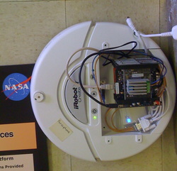 One of the iRobot Creates with extra electronics One of the iRobot Creates with extra electronics My responsibilities as the mechanical engineer for the project was to design and create the integration of the electronics which allowed wireless communication between the central computer and each robot. Mechanically, I had to get the electronics mounted onto the robot. This included the Freescale "Tower" which contained the real-time processor and a board with a network adapter. Also there was the wireless router / adapter, and the voltage regulator. Early models needed a laser level as well. Electronically, I had to design and make cable adapters to transfer power and data between the robot and the added electronics. I also had to design and make the cables that connected all of the various components. The space available inside the robot was tight, and I attempted to make the profile as low as possible, which made routing the cables more challenging as well, and required creativity so they could fit. Being able to build each robot allowed me to work hands-on with the hardware rather than on the computer. Actually putting it together also provides the feeling that you are making a lot of progress and is a great thing to do whenever something else is frustrating. The biggest challenge was doing location determination for the robots, many techniques were tried, but in the end none of them worked. The first approach was to use lasers, which fanned into a line on each robot, and light detectors in different spots of the room to trilateralate the position of the robots, but we could not find lasers who matched frequencies with the detectors or vice-versa. Additionally the laser on each robot was not very powerful, so within a few inches it would no longer pick up the signal, even in the dark. About the same time I was pursuing this technique I encountered a lot of problems with signal processing on the computer side as well, and the difficulties of trying to use Labview in real time to detect pulses. Labview is great for a lot of things, but I could not be great at identifying signals and processing them in real-time. The next approach was to use the diode "walls" which came with the iRobot Create. The thought was that we could detect the walls ourselves with the IR sensor on the Create and determine the location of the Creates as the direction of the IR beam spun around the room. In theory it would work great, but there were more difficulties. The difficulties which this ran into was the ability for the Create to send data back to the computer, which had a lot of problems with interference chopping the packets into pieces. The second problem was the range of the walls, which could not be made good enough to determine their location within a decent range, although it was better than before. Precision had always been a problem with this approach before as well. I tried to collimate the IR LED as best as I could, but it would never be good enough for what we actually wanted, which was plus or minus a few centimeters at a range of about 10 meters. Location detection was never something that could be implemented in the robots, and by the end of our 5-week project we were unable to make them location-aware, although the other goals of coordinated movement and wireless communication were met. As I waited in the airport for my flight out of Huntsville, I was talking to a member of the all-graduate student team which was also part of the NASA Robotics Academy about my frustrations with the hardware available to us as interns and the difficulties of my project. I told him that I thought the best way to press forward in the future was to use sonar to track the distances and trilateralate the positions of the robots. He told me about an amazing system which is called CRICKET, developed by MIT to ultrasonically locate the positions of robots with centimeter accuracy in an indoor environment. As it turns out, they developed exactly what I was dreaming about. I think the biggest lesson I learned this summer is that even if it seems like time is very limited and you must charge ahead down one path that looks easy, it is good to ask yourself if it is the best way to do it, and approach it with a somewhat cynical mind so I can identify problems earlier. It is also good to seek help whenever encountering a problem, especially from those more experienced than you, even if you think you have it figured out, because you just might not. Despite the setbacks in location determination, using dead reckoning we were still able to get the robots to move together, both independently and simultaneously. This project succeeded in all other areas of development, and was a sucess. It may be continued by robotics academy students next year. |
Lars OsborneBS Mechanical Eng Categories
All
|

 RSS Feed
