|
I recently discovered a small, but lovely community called STEMN, the Science, Technology, Engineering, and Math Network. It is a collaboration tool for people all over the world to contribute to space projects. People post projects and questions and get feedback. and answers. I have seen a lot of student CubeSat projects there, and while students (as expected), have a lot to learn, I have noticed that many of them struggle more in the area of thermal analysis. That is why I made a tutorial to help students understand the thermal environment, perform basic analysis, and design for passive thermal control.
1 Comment
Left: First prototype. Using the arduino clock only, powering a single RGB LED
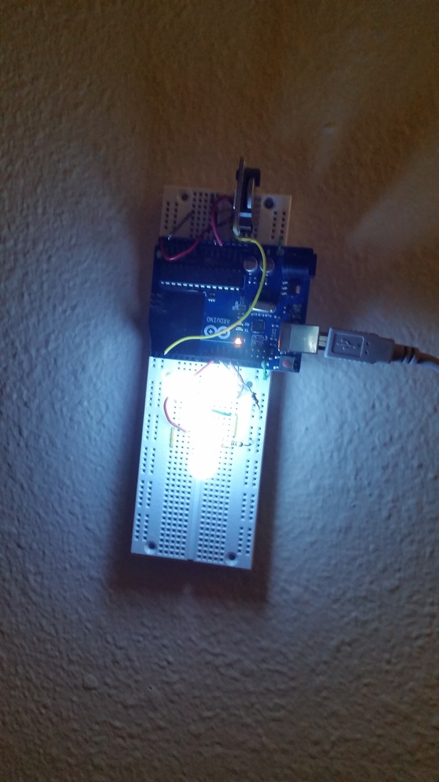
Right: As it is today, real time clock module (top) and 5 powerful white LEDs 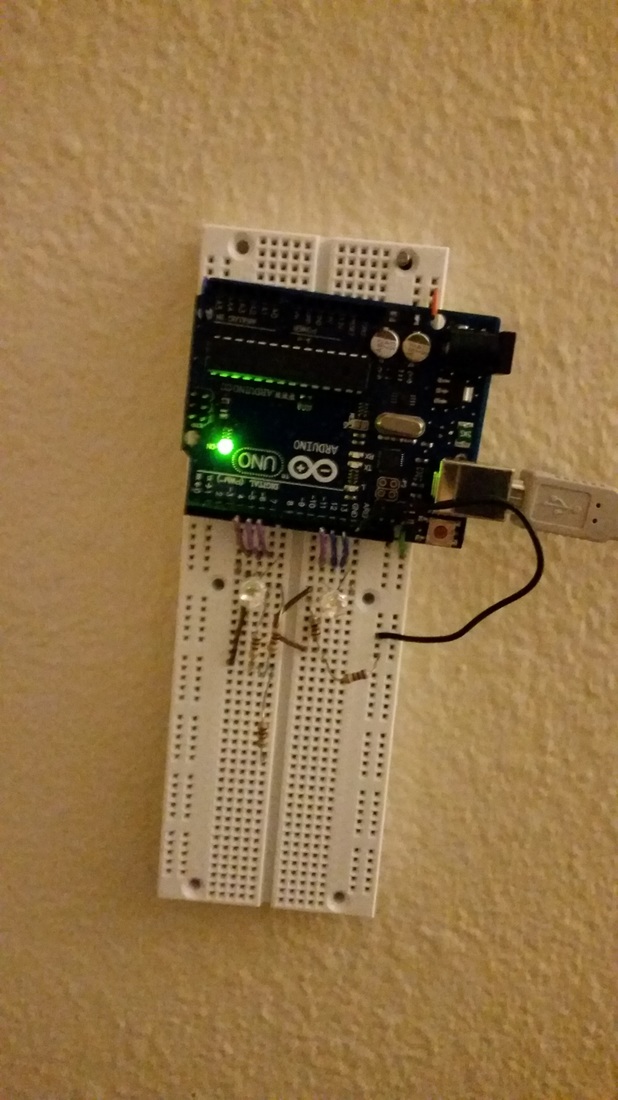
Being from Fairbanks, Alaska, I am used to the fickleness of the sun from season to season, and have coped with many mornings of waking up when it was pitch black outside. Seattle gets a more daylight in the winter months than where I grew up, but the rain and clouds doesn't make it much better.
I wanted a light alarm clock to help me get out of bed on those dark dreary mornings. I had looked for a luminous alarm clock online, but didn't like any of them. They were all large, counter-top clock-radio devices with big LCD screens and features I didn't want, without the ability to be programmed on a clever schedule. I decided that it was a simple enough thing I could make on my own. This was a small project, and also one of the few I have ever completed in a single weekend. I had considered using an internet-connected spark core for this project, but I had another use in mind for my one and the power output is rather low. Being internet connected could have made time-keeping much easier, but chose to use an Arduino Uno because I had a couple of them laying around and knew it would be able to pack enough of a punch to light up many LEDs. Friday night I quickly prototyped the device on a breadboard with an RGB LED I had in my stock, and just using the Arduino's timer, I was pleasantly surprised to see that it was on the following morning! An arduino's built-in clock is not adequate for time keeping and would become wildly inaccurate over a few weeks. I upgraded to the DS1307 real-time clock with a coin-cell battery backup. It tracks time and communicates to the arduino over an I2C bus. If you happen to be using that same device, I discovered that Vbat and Ground do need to be shorted together. Otherwise, the clock will report a time, it just won't increment it. I soldered on a 90 degree header strip and plugged it into my breadboard vertically. The LED's are in a 10mm package and run on 3.2 V with 20 mA of forward current. I chose bright white to help me wake up faster. I bought 9 but I stopped wiring after 5, and it seems to be enough to get me out of bed. I choose to keep them on from 7 am to 9 pm, to give the bedroom a little more light during the day. After a frustrating few hours of software debugging I concluded that the battery backup for the real-time clock was not functional. I haven't dug very deep yet, but in the spirit of rapid prototyping I wanted to sprint to what would be good enough for the next morning, and make fixes as needed later. I programmed the RTC with the correct time when it was plugged in, and it would keep time from there. This will be just fine unless power is interrupted. In the Seattle area, with it's abundant hydroelectric power, outages are very rare. Code:
The debugging statements and planned features are left in. I found the serial output commands to be very useful when debugging. I borrowed the bulk of this code from another tutorial, the source of which I cannot find right now.
After falling in love with the idea of having my own factory on my desk, I finally got a 3-D printer. The significance of having a 3-D printer is not that I simply have another toy. It isn't even that I have a new tool that will allow me to make things that I can dream up or that I will be able to gain experience in design tolerance and go from ideation to prototype. I think the real significance of my 3-D printer is that I know I am joining a movement that will have a hug impact on our economy and culture, and will probably be as big as the computer revolution. The ability for individuals to manufacture their own objects and products in their own home will drastically change consumerism and will probably have a big change on intellectual property rights when consumers have the ability to make physical objects. I chose to get a Makerbot Thing-o-Matic because the company has heritage in building low-cost 3-D printers and because they are a for-profit company so I knew the product would be supported. I could have gotten a RepRap for significantly cheaper but decided against it just because of the challenges that I have faced in the past when working with open-source projects. Another cool feature about the Thing-o-Matic is that it comes with an automated build platform, which allows me to print many objects in a row without my interference. I could leave it home printing all day while I am at school. It will really let me get creative in making things, like last-minute parts for my capstone project, camera mounts for rockets, actual rockets, small design projects, and of course the rapidly growing collection of things that already reside on Thingiverse.com Slide-show below showing the build process (in reverse order for some reason). As an early adopter may expect, the instructions for assembling the makerbot were not always good as one might like. The instructions were entirely online, which is good because a paper copy would probably weigh a significant amount, and I was content to just read them off of my screen. As the Thing-o-matic has been revised and changed piece-by-piece, one could tell which instructions had been written for earlier models by their clarity. The newer instructions were quite helpful with lots of pictures, but the old ones occasionally left us scratching our heads - though usually not for long. Luckily there were user posted comments for every page of the instruction manual, and those pages were well organized.
The instructions claimed that it would take about 16-20 hours to complete. Although I did not time myself, I believe that it took longer than that for myself. Ellen Farber assisted for the entire first half of the project, and then I continued on my own. I found during the final stages that it became easy to make mistakes during assembly, and there were a few times that I had to take apart major sections. I had the body panels accidentally reversed a few times, before finally coming to a configuration that works. It was magical when I first turned it on and a thin string of semi-molten plastic emerged from the extruder. The most challenging and the most frustrating part of the entire process was the calibration of the machine after it was completely built. This took the most amount of time. The bug that kept getting me was a 'slipping' of the Y-axis during some builds. Eventually, I discovered was because I did not have stepper motor types I thought I had, and the stepped motor controllers had not been adjusted to the right settings. The next challenge was spool management. This is a serious issue until you can print the parts that are needed to keep the spool rolling and in the right place. My biggest challenge at the moment is dealing with warping on the build surface. As it turns out the Automated Build Platform results in a significantly reduced quality of the print in exchange for automation. The belts also wear out over time, making things worse. But the absolute worst thing about the ABP has to be that you cannot level it. It is front heavy because of the DC gear-motor, so the little bit of slop in the rods throws the whole thing front heavy. I am trying to weigh my options, which are 1) Buy the heated build platform in addition to the ABP, 2) Get a titanium belt for my prints (about the same price) or figure out something else.  So, it is clear that the ejection charge was not able to save the rocket from destruction, and it did not go off until it went below the trees. When the pieces of the rocket were recovered, it landed about 435 feet away from the launch pad. That makes me feel pretty good knowing that it was that far away from everybody. After studying the wreckage and where all of the pieces landed, I think that I can completely determine what happened in the few moments before impact. We lost visual sight of the rocket in the trees, and never saw the ejection charge fire. However, from the soot and black-powder remnants left on the rocket I can conclusively determine that the ejection charge definitely went off before the rocket split up. I believe what happened at this point was instead of ejecting the forward section from the interstage and deploying the flagging to slow its descent, it instead blew the rocket apart right before the interstage, keeping the forward part of the rocket and the interstage together. The flagging, sadly, was ripped to shreds by the shock and small pieces were scattered around the area. When exposed to the cold the flagging became much more brittle than I had expected. Once the rocket was split into two pieces, the aft piece of the rocket was still composed of three layers of cans. The middle layer made contact with a dead tree, puncturing a can and separating it from the other two pieces. I reasoned this from the lack of damage on the other two layers of the aft section, and the placement of all three layers. There was also an ugly looking dead tree that was in just the right place for it to all make sense. Captions under full-sized images. 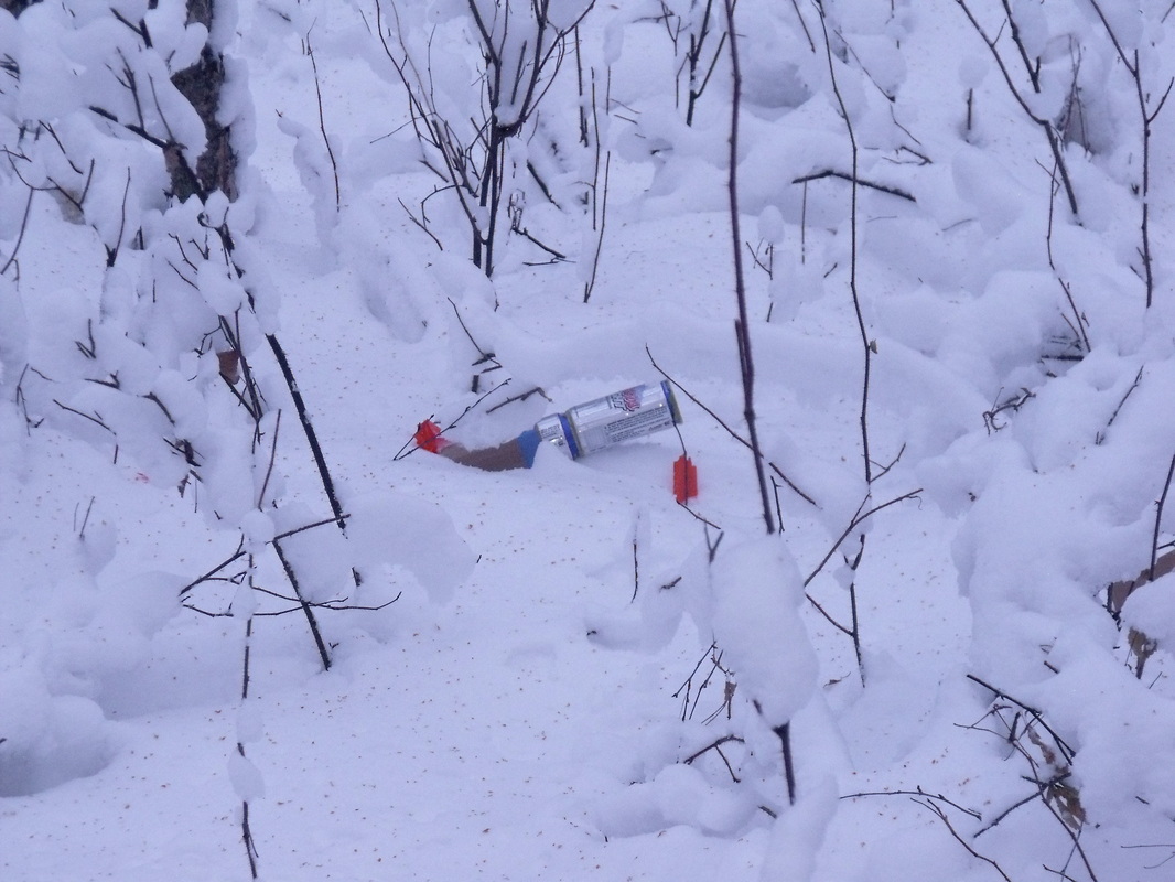 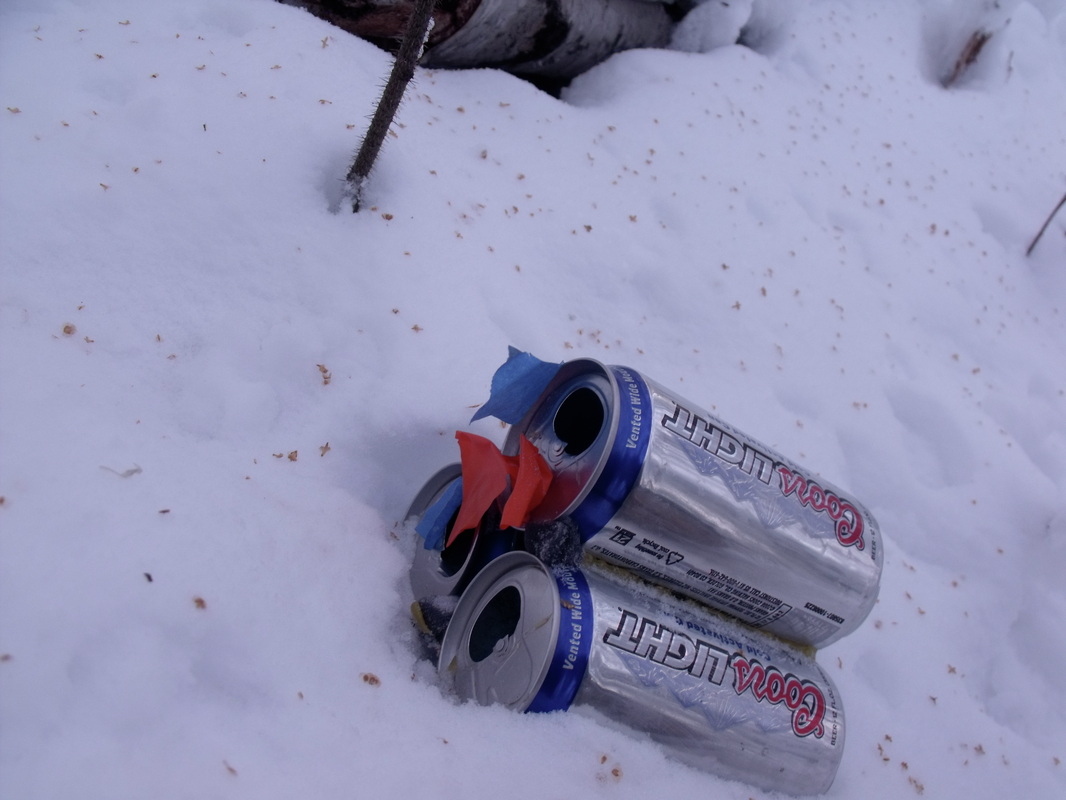 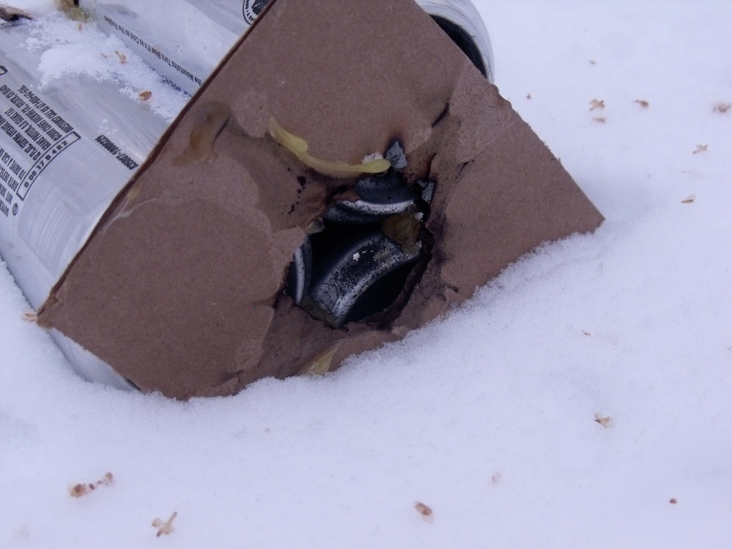  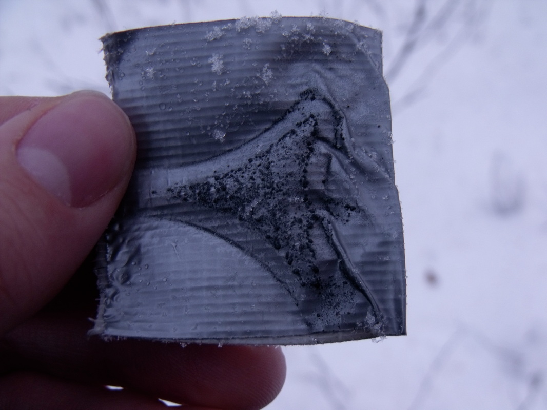 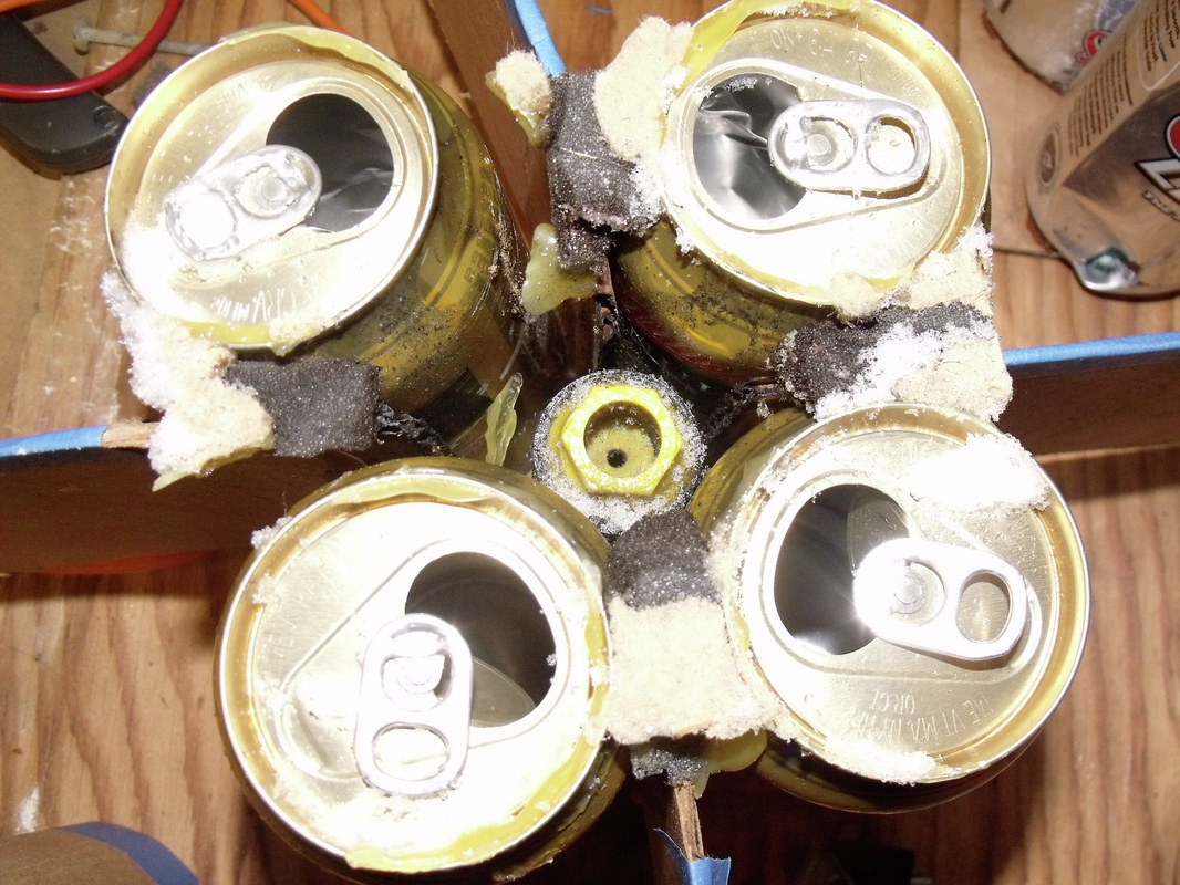 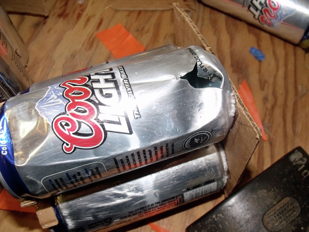 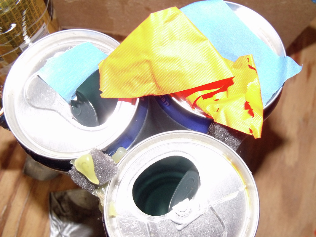 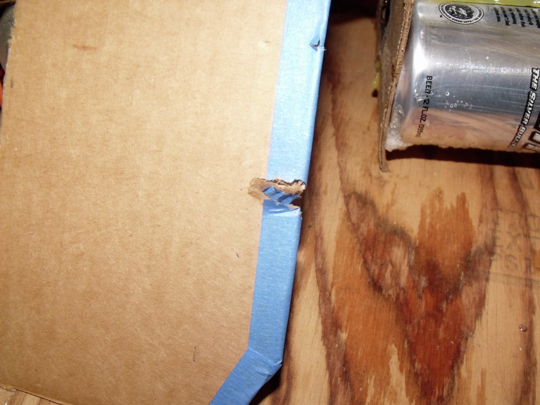 The only piece of the puzzle that I was not able to satisfactorily figure out is what happened to the nose cone of the rocket. I tried looking around for it pretty hard, but was never able to find it. I may try again during the summer, although I think I would be even less likely to find it then.
I wanted to do something while I was home on break from school. While my initial plans were totally different and more complex, I think I can be proud of the recycled rocket. This was meant to be a continuation of the Coors 1-X beer can based rocket body, and act as a stepping stone to the Coors V, allowing me to experiment with a transitions between can configurations that differ between levels. For example, this rocket transitioned from a level of 4 MGD cans to two levels of 3 Coors Light cans then to two levels of single Coors Light cans and finally to a bottle of Alaskan Oatmeal Stout for the nosecone. I was able to obtain some F20-4W (20 newtons average thrust, 4 sec ejection charge delay after burnout, white flame). I also collected as many beer cans as I reasonably could. This rocket became known as the "Recycled Rocket" because I used much more than just beer cans, relying heavily on cardboard for the construction of not just fins but also stage adapters and interstage. Recycled paper was used for the aerodynamic nose cone; This rocket was made out of 100% post-consumer waste, excluding the tape, epoxy, hot glue and rocket motor. The first photo gallery shows some of the construction of the rocket. (click images for captions) 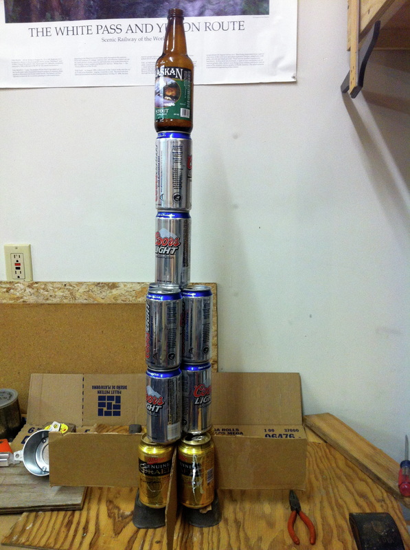  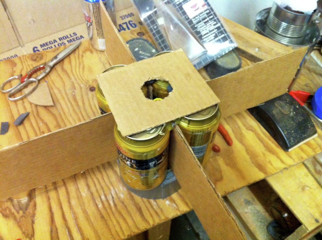 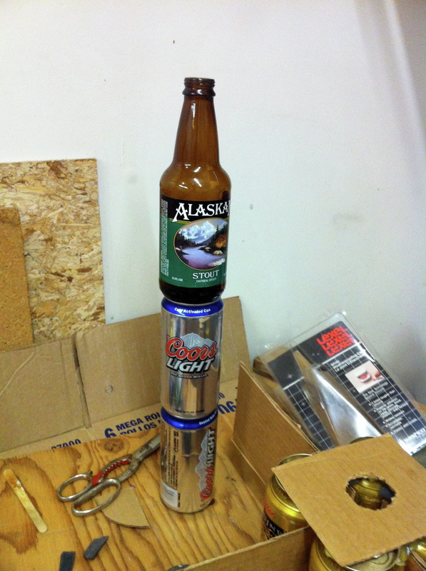 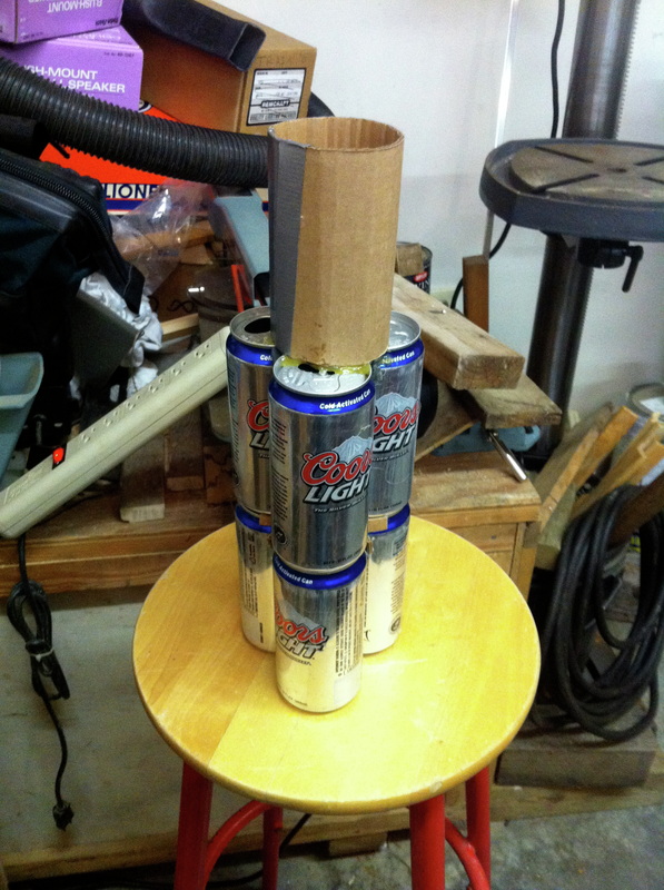 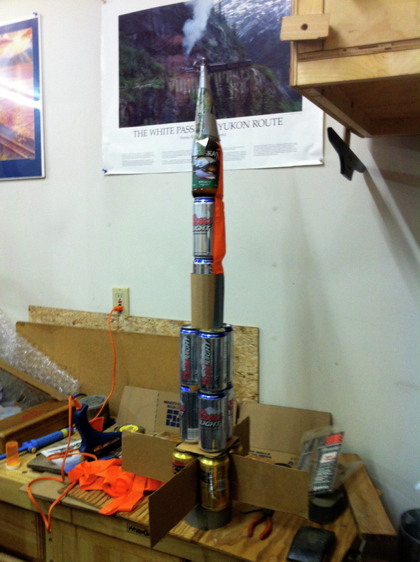 So admittedly, some of the criticisms of this project could of course be the use of glass in the nose of the rocket and the lack of a slow-recovery system. In defense of such possible criticism, the reader should be made aware, and can see in the videos of the rocket launch, that the launch range used was entirely private and massive (several miles of possible range), and the rocket was launched at a lower QE (launch angle WRT normal) to get as far away from structures or observers. Video of the Launch: 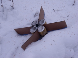 'Recovery' 'Recovery' You can see another video from a different angle here.
Unfortunately the aspect ratios which I captured that at didn't allow me to edit it using iMovie 6. That's what I get for holding my iPhone vertical I guess. It is impossible to see the apogee or descent of the rocket in these videos unfortunately, but the rocket was sufficiently heavy that it went behind the trees before we saw an ejection charge. I made some guesses at the coefficient of drag of the rocket, and using Excel modeled a 1-dimensional flight path of the rocket. that model seems to have since been corrupted, but I think I estimated an upper limit apogee of around 300 m or more. With negligible drag in free fall, this would mean about a 4 second fall. Including the coast time of the rocket, the ejection charge was never going to fire very high anyways due to the large weight of the motor. Unfortunately adjusting the delay timing was not possible. I will have more on the recovery and crash analysis next post. |
Lars OsborneBS Mechanical Eng 
Categories
All
|
 RSS Feed
